📅 Friday, May 3rd, 2024
The more you know yourself, the more you forgive yourself.
— Confucius
ECS154A: Lecture: timing
- ”idealized” timing diagram: all transitions are instant (horizontal - vertical - horizontal) — impossible (infinitely fast transition)
- conventional timing diagram: slope transitions, with cusps, still technically impossible but practical
- ”real” timing diagram: sigmoid-looking graph
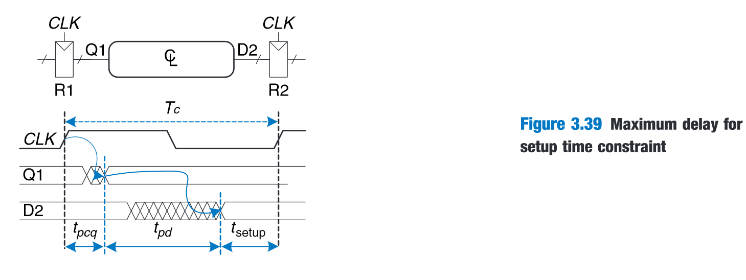
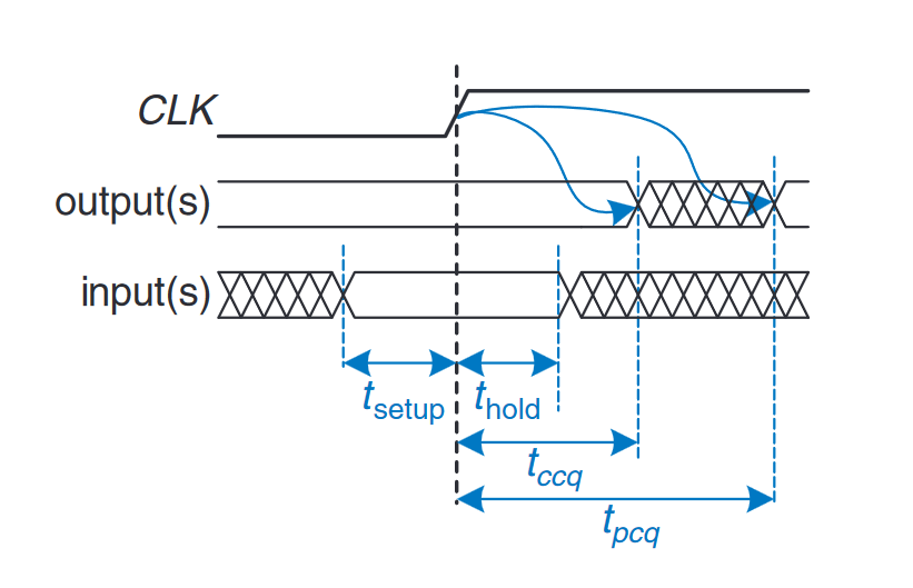
lecture’s convention for (max) propagation delay:
lecture’s convention for (min) contamination delay: . Min delay violations can really mess up sequential circuits.
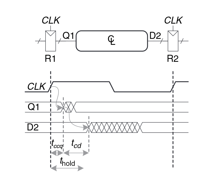 The short path (path with least delay) decides the circuit’s contamination delay, and the critical path (path with highest delay) decides the propagation delay, which is critical to the timing of the circuit.
Aperture time () is the combination of the setup time and hold time, which are time constraints that require the circuit inputs to be stable before (setup time) and after (hold time) the clock signal / positive edge.
ECS154A Discussion: timing cont’d
There are two parts of combinational logic in a sequential circuit, one that determines the next state from previous state and inputs, and another one that determines the circuit outputs for the current cycle.
Moore circuit: output depends on next state only. “Less is Moore” (Moore circuits require less to compute the output)
Mealy circuit: output depends on next state and some inputs to the circuit
Sequential circuit design process:
- Create a state transition diagram
- Create a state transition table
- Come up with equations for (simplified with K-maps, etc)
- Decide how states should be mapped to outputs. Come with equations for outputs via K-maps, etc.
- Design a circuit with the inferred equations, using one register for each state bit.